Roads and Culverts Improvement Plans Drawing List
A set of construction drawings consists of the general organization drawings supplemented with detailed superstructure and substructure drawings and other fabrication, cloth, and construction specifications.
It may be appropriate in some cases for the Ministry Engineer to take on the CRP part, given that engineer's familiarity with the initial decisions for the project. Even so, the bridge engineer's fourth dimension constraints may preclude this option. If the Ministry Engineer is non the CRP, accept the Ministry Engineer review the structure drawings (a combined package of general arrangement and structural drawings, including erection loads) and the FS 137 Assurance of Field Reviews and approve them every bit meeting the ministry building'due south design and structure requirements.
Shop drawings are prepared by material fabricators to particular, and in many cases, complete the structural design of bridge construction components. Ensure that these drawings are retained as function of the as-built documentation. The complete construction drawing set provides comprehensive details on the location, limerick, arrangement, design parameters, and fabrication, materials, and structure specifications for the specific proposed structure.
On the structure drawings, conspicuously show all construction details and provide for installation in general conformance with the design intent.
four.10.1 General Span Arrangement Drawing Requirements
Ensure that general arrangement drawings clearly depict the proposed components and configuration of the span or major culvert in relation to the woods route, stream, and streambanks. Also, use these drawings during the agency referral process (see the Woods Service Bridge Blueprint and Construction Manual).
Ensure that the contents for bridge and major canal general arrangement drawings include:
- site location key map;
- designer's proper name (and seal);
- proper noun of the stream, road, and station (km) and adequate information to detail the location of the structure;
- design vehicle configuration for load and alignment;
- design code references, specifically those from the well-nigh recent version of the CAN/CSA S6 – Canadian Highway Span Blueprint Code and the Canadian Foundation Engineering Manual;
- expected life of the structure in identify (temporary or permanent);
- design high-water pinnacle for bridges and design discharge;
- clearances between the design high-water level and soffit (depression betoken of underside of superstructure) of bridges;
- details of debris passage or management strategies, if required;
- road approaches and grades, including width requirements (e.g., allowance for vehicle side tracking) and side slopes, to a sufficient distance back from the bridge to show potential problems, or to the end of the outset cut or fill up;
- dimensioning and labeling of component parts (to be confirmed with the shop drawings);
- connexion requirements for component elements;
- drawings scales;
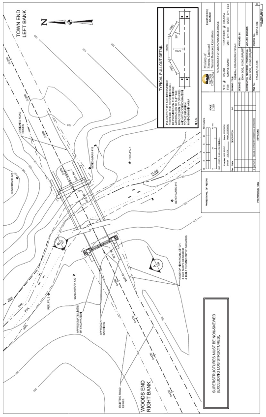
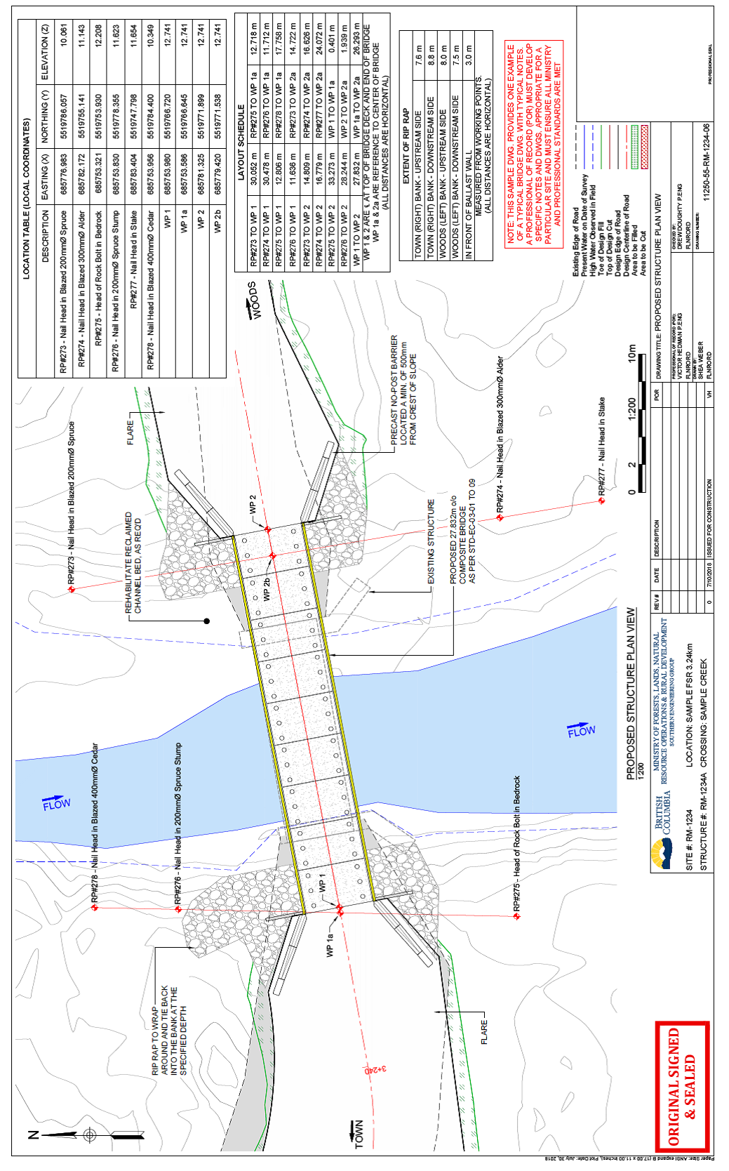
- relevant site plan and profile data (for suggested contents, come across Site Data & Survey Requirements for Bridges & Major Culverts; sample general arrangement drawings are shown following in Figure 4-one and Effigy 4-2);
- location (vertical and horizontal) of proposed structure relative to field reference points;
- deck elevations at bridge ends;
- possible ford or temporary span crossing locations;
- road and bridge or canal signs;
- arroyo barriers, if required;
- rip rap extents;
- limit of construction for contract purposes;
- special provisions related to the unique nature of the site and crossing, including specific instructions to bidders related to process or results, as advisable;
- special instructions relating to cloth erection, installation standards, requirements, or methods as deemed necessary.
Figure iv-1 Sample of General System and Layout (simple creek crossing) (PDF, 6.03 MB)

Figure 4-two Sample of General Organization and Layout (complex creek crossing) (PDF, 2.2 MB)

4.10.2 Span Superstructure Drawing Requirements
Item the following elements on span superstructure drawings:
- design code references, specifically those from the latest version of the Tin/CSA S6 – Canadian Highway Bridge Pattern Code and the Canadian Foundation Engineering science Transmission;
- individual member shapes, dimensions and connection details;
- materials specifications and CSA references, including but not limited to:
- steel grades, impact category, finish;
- timber species, grades, preservative treatment;
- physical forcefulness, slump, and air entrainment;
- begetting materials and connections;
- superstructure elements, configuration, and connections;
- dimensions and sizes of components;
- girder or stringer arrangements and connections;
- bridge lengths;
- bridge and road width;
- curb and runway configuration, connections, and component elements;
- span label with structure number, appointment of manufacture, and load rating; and
- field fabrication details.
Note that the superstructure drawings are commonly supplemented past shop drawings prepared by the fabricator.
4.10.3 Bridge Substructure Drawing Requirements
Ensure that the following information on foundation requirements is detailed on the bridge substructure drawings:
- abutment elements, configuration, and connections;
- dimensions and sizes of components;
- critical elevations of substructure components;
- scour protection: dimensions, composition, extent of placement, design gradient, design loftier water, and other considerations;
- piers;
- location and sizes of piles or posts;
- pile-driving specifications, minimum expected pile penetrations, set criteria, and required service level capacities;
- field welding requirements;
- bracing and sheathing configurations; and
- foundation requirements, material types and depth, and compaction level.
The above requirements also apply to portable span superstructures.
4.10.iv Log Bridge Superstructure on Log Crib Drawing Requirements
Since log stringer and crib materials are variable in nature and finished dimensions are not uniform, log span drawings are somewhat schematic. Ensure that the drawings address layout of the structure and its elements, required component sizing, and connectedness details.
Ensure that the following are indicated on the log bridge superstructure and log crib drawings:
- schematic layout indicating width and span;
- reference source for stringer and needle beam sizing;
- minimum stringer, curb, and needle beam dimensions;
- stringer, adjourn, needle beam, and crib logs specifications, including species, quality characteristics of acceptable logs, and seasoning;
- stringer-to-cap bearing details, including shim types and stringer and cap- bearing width and surface training;
- dap details at log connections;
- needle axle locations and connectedness details, if applicable;
- space to add stringer, curb, and needle beam sizes every bit part of the every bit-congenital record;
- deck layout, indicating tie sizes and spacing, plank thickness, and connections;
- other materials specifications, including sawn timber, hardware, and shims;
- excavated depth relative to scour line for mudsill or bottom bearing log;
- general layout and system of forepart, wing wall, deadman, and tieback logs, and their connections to each other and to the begetting log or cap;
- description of crib fill textile;
- layout and description of in-stream protection, if applicable; and
- rip rap protection layout and specifications (as required).
4.10.5 Major Culvert Cartoon Requirements
Ensure that drawings and notes for major culverts portray and describe the following:
- site plan (see Site Data & Survey Requirements for Bridges & Major Culverts)
- location of the culvert, such as a key map;
- design vehicle load;
- fill height, depth of comprehend, and maximum and minimum comprehend requirements;
- pattern slopes of make full and rip rap;
- canal invert elevations at the inlet and outlet;
- canal specifications and dimensions: opening dimensions, length, corrugation profile, judge, material type, and inlet bevel specifications;
- site training requirements;
- embedment requirements, including a clarification of the substrate and whatsoever stone used to ballast the bed material in the pipe;
- foundation details;
- backfill and installation specifications;
- installation camber;
- canal gradient;
- seepage barrier details if required;
- special attachments or modifications;
- inlet requirements (rip rap layout, stilling bowl, etc.);
- outlet requirements (rip rap layout, stilling basin, backwater weir for fish passage);
- rip rap specifications, including dimensions and configuration;
- design loftier-water peak and design belch, inlet or outlet command;
- connection details for pipe sections; and
- any existing improvements and resource values in the vicinity of the culvert that would influence or be influenced by the structure.
Combine whatever of the higher up requirements may where appropriate. For example, drawings for a log stringer span on timber piles may include the details from Log Bridge Superstructure on Log Crib Cartoon Requirements, plus those from Bridge Substructure Drawing Requirements.
Include whatever additional requirements for a fish stream culvert, as specified in the Fish-Stream Crossing Guidebook (PDF, 4.2MB).
iv.x.6 Portable Span Superstructures
Where portable span superstructures or other structural components are used for any FS bridge project (including those bridges built under Road Let (BCTS) and designated in that permit to be an FS bridge to be used for harvesting later completion of the Timber Auction License), the components must have been designed or structurally analyzed past a professional engineer, to demonstrate adequacy for the intended utilize.
Record the ministry portable bridge superstructure number or, if there is no current superstructure number, contact the ministry engineer so that 1 tin can be assigned.
Once the components have been reviewed and canonical past a professional engineer, re-utilise the components at new sites without specific professional engineer review of the superstructure, provided that:
- a qualified inspector has inspected the bridge at the new site before whatsoever use and does not detect whatever harm or deterioration of the structure; see Affiliate 6 Engineered Structured Inspections - Types of Inspections;
- the blueprint loads to exist carried are equal to or lower than the original pattern loads for the superstructure;
- the span is suitable and has been specifically designed or analyzed for the new site, and signed and sealed blueprint drawings and specifications accept been prepared; and
- the superstructure has been fabricated and constructed in compliance with the advisable legislation.
Source: https://www2.gov.bc.ca/gov/content/industry/natural-resource-use/resource-roads/engineering-publications-permits/engineering-manual/design-construction-bridges-culverts/construction-drawings-specifications
Enregistrer un commentaire for "Roads and Culverts Improvement Plans Drawing List"